LF PICTURE TOUR
Piston and Stabilizer

Piston vs. Stabilizer Bar Friction
The piston shown is 4 inches and is in a cylinder that has had the surface honed to hold oil. This increases the coefficient of friction greatly.
The stabilizer bars are 3/8 inch diameter and are coated with diamond like coatings to reduce friction. The retainer plate that the stabilizers bars pass thru have brass bushings that are lubricated for low friction
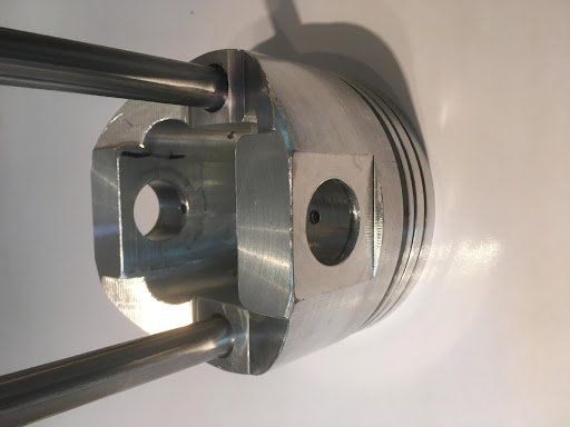
Piston with Stabilizer Bars Attached
The piston is designed to hold two stabilizer bars. The skirt is eliminated and the piston lightened accordingly. Titanium wrist pins and titanium stabilizer bars are used. Each has a special coating to reduce friction and wear.
Retainer Parts
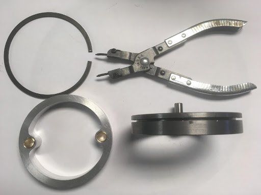
Retainer Collar, Retainer Ring, and Removal Tool
The collar is designed so that it can be easily removed using standard ‘C’ ring pliers
The retaining ring is a standard piston compression ring with holes drilled in the ends
The retaining ring allows the collar to turn, but not to move up or down in the cylinder
The bushings in the collar hold the stabilizer bars is a vertical position
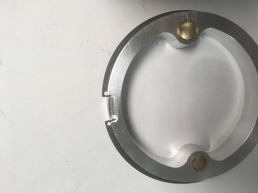
Retainer Collar Detail
This picture shows the retaining ring in place. The retaining collar is machined to have an opening to allow a tool to remove the collar. You can see the two holes that the ‘C’ ring pliers fit into.
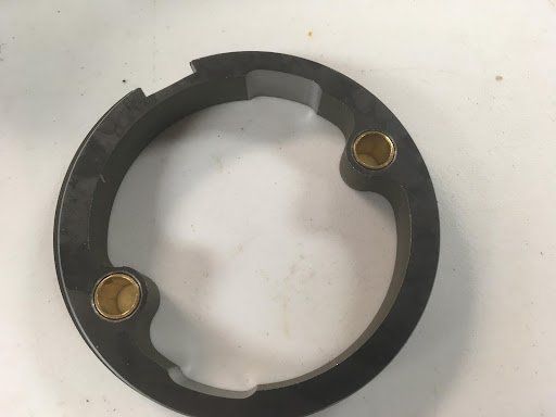
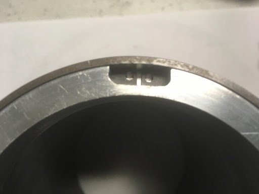
Retainer Collar Inside Cylinder
The retaining collar is shown installed in the top of the block, but not pushed down far enough to ‘click’ in place. You can see the machined opening and the two holes in the retaining ring. Inserting the tips of the ‘C’ ring pliers into the two holes and squeezing will allow the collar to be removed.
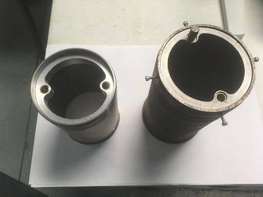
Two Wet Sleeves with Retaining Collars
The wet sleeve on the right has the retaining collar installed near the bottom of the sleeve. Here an early version of removing the collar was used and a short rod inserted in one bushing. The sleeve on the right is our current technology.
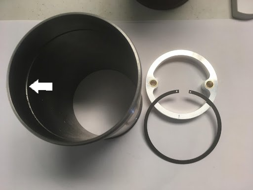
Cylinder Wall Groove
The .030” groove in the cylinder wall is shown in the cylinder near the arrow. The retaining collar and retaining ring are shown to the right of the wet sleeve.
Connecting Rod
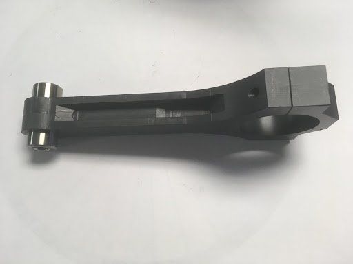
Special Connecting Rod
Shown is a prototype of the new connecting rods that will be used in LF engines. The picture that follows shows the fact that the stabilizer bar fits into the gap in the connecting rod. This is a critical part of the design. Titanium connecting rods are preferred, but not necessary.
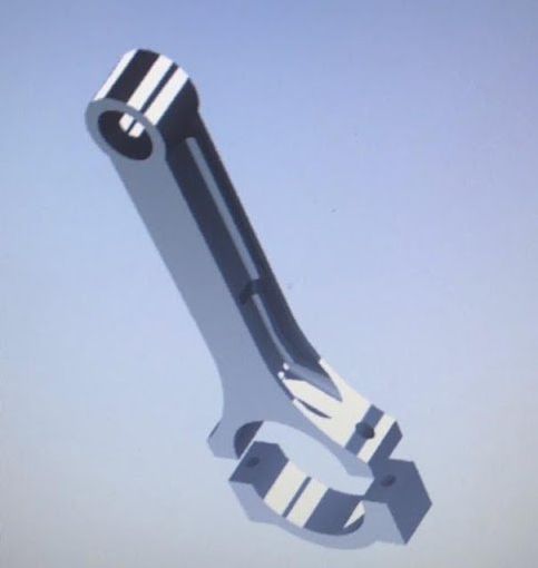
Special Connecting Rod, Solid Works
Shown is a Solid Works rendering of the new connecting rods that will be used in LF engines. The rendering shows the fact that the stabilizer bar fits into the gap in the connecting rod. This is a critical part of the design.